MAGIC SWITCH CHROMA
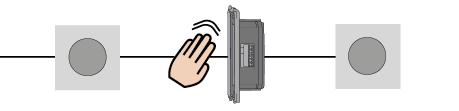
The Magic Switch is a touchless opening sensor for automatic doors. One hand motion in front of the sensor opens the door, completely contactless. Therefore, it is the perfect knowing act sensor for applications where hygiene is essential: hospitals, clean rooms, hotels & restaurants, pharmaceutical industries, airports, logistics and retail.
|
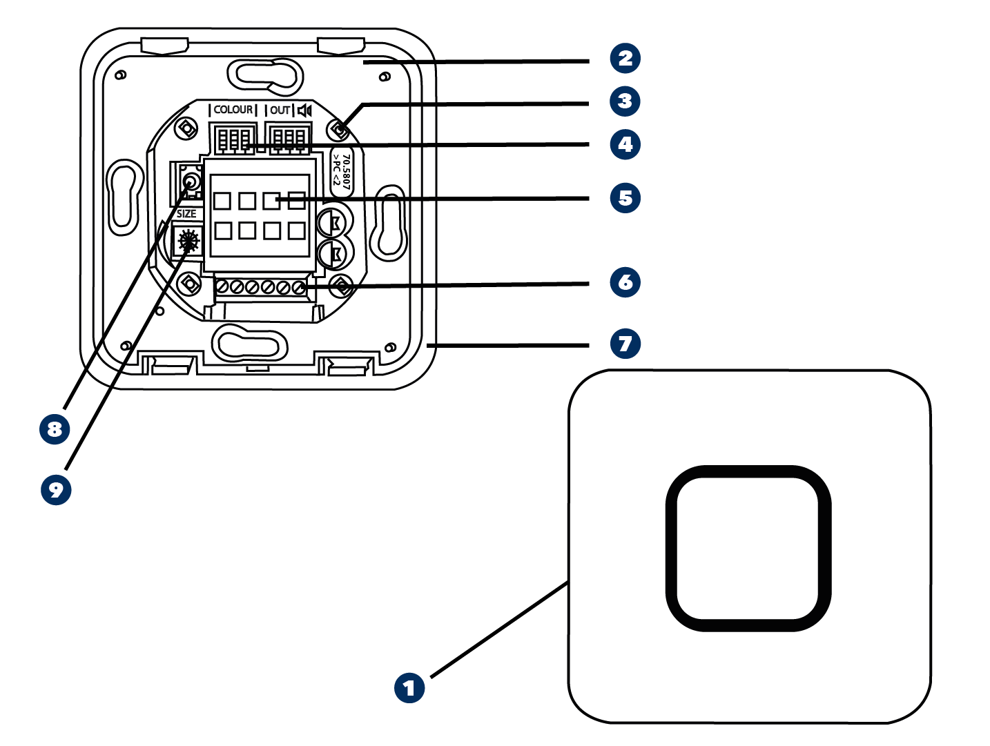
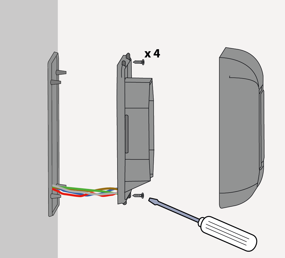
RECESSED INSTALLATION | ||
|---|---|---|
 | ||
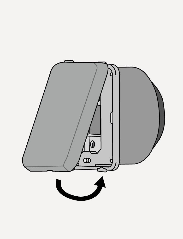
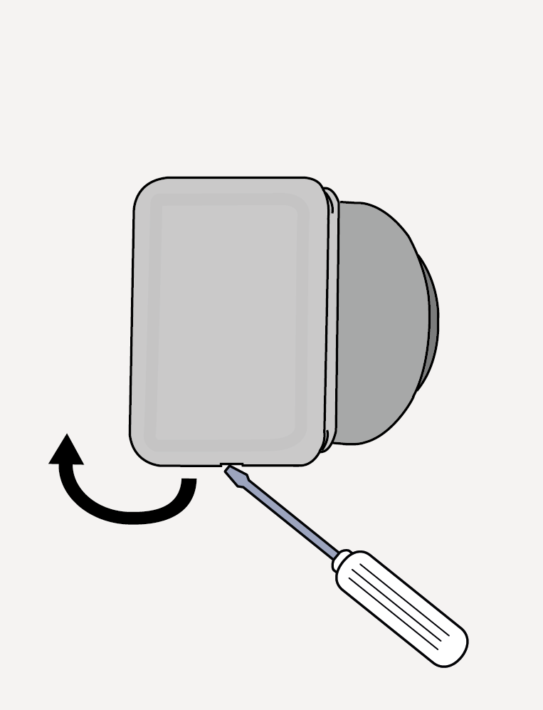
SURFACE INSTALLATION | ||
|---|---|---|
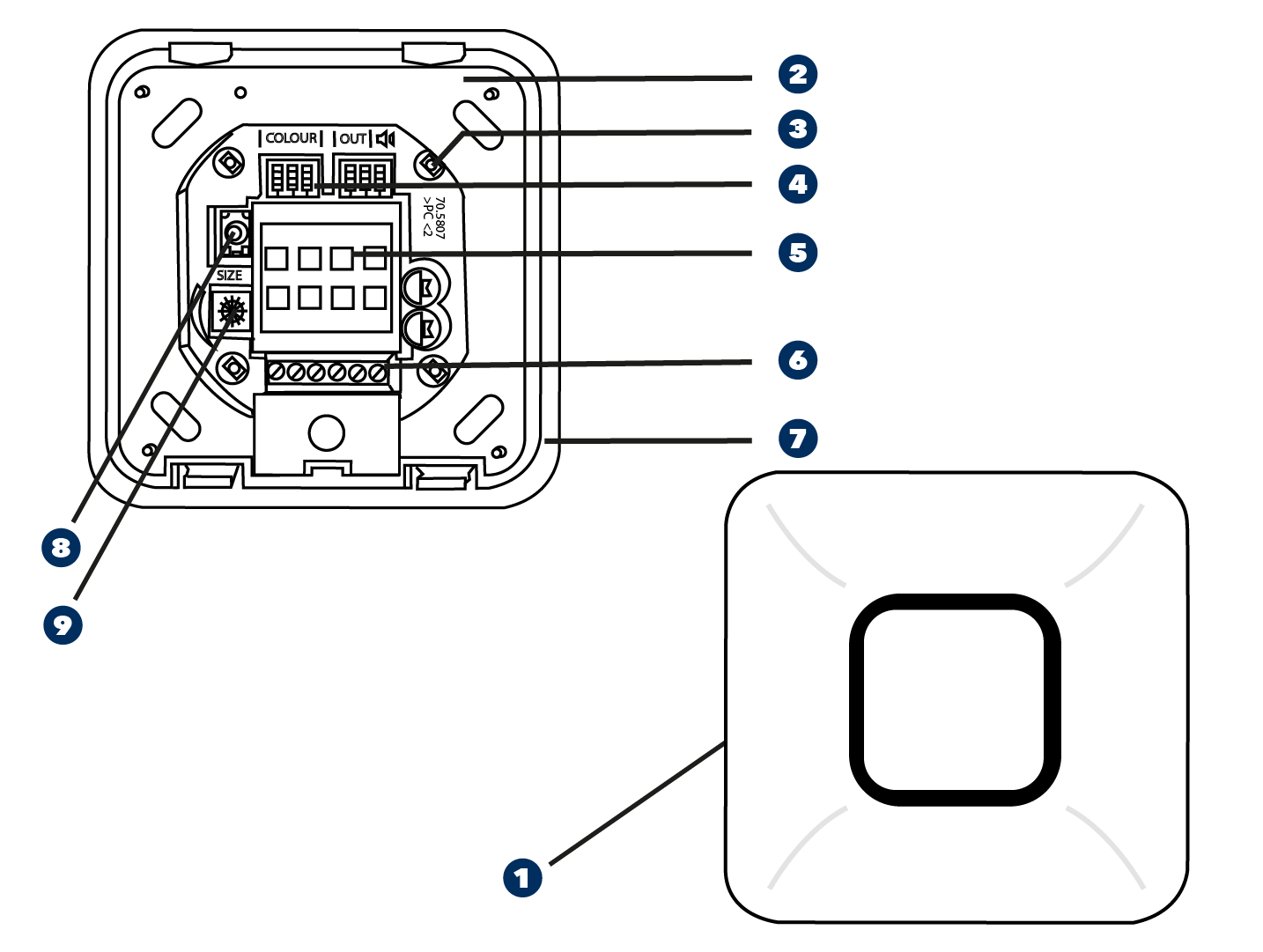 | ||
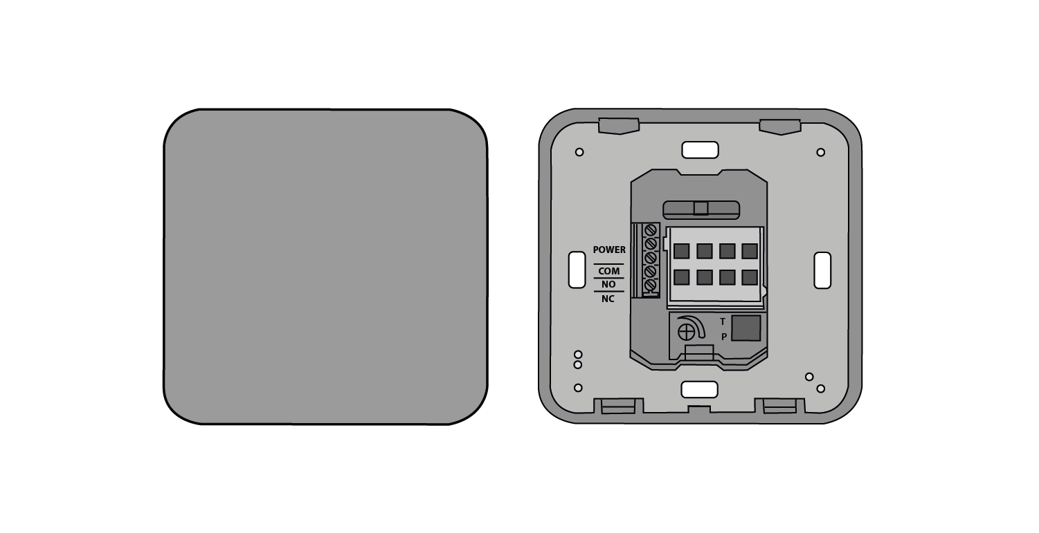
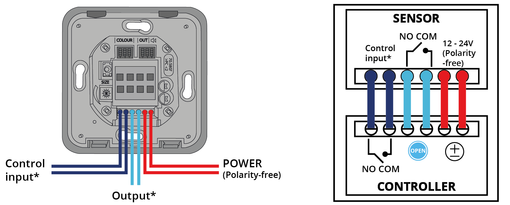
 | Front face |  | Terminal block |
 | Fixing frame |  | Gasket/seal |
 | LED (4x) |  | Remote control receiver* |
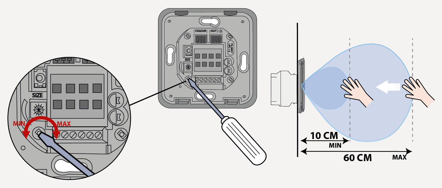
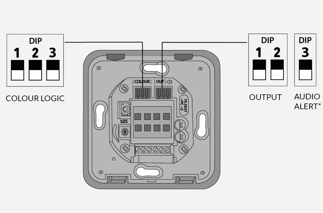
 | Dip switches |  | Field size adjustment |
 | Antenna |
STANDARD VERSION | ADVANCED VERSION | ||
|---|---|---|---|
 | Antimicrobial front face | | Antimicrobial front face |
 | Multicoloured LED-feedback | | Multicoloured LED-feedback |
 | IP65 | | IP65 |
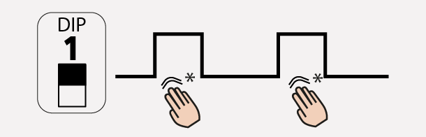
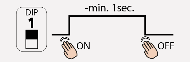
 | Toggle-function | | Toggle-function |
 | Audible feedback | ||
 | Remote control adjustments (see remote control settings annex) | ||
 | Settings for specific application through external signal input | ||
RECESSED INSTALLATION | SURFACE INSTALLATION | CLOSE | OPEN |
 |  |  |  |
|
|
|---|---|
 |  |
*available only in the advancer version |


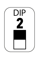
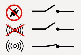
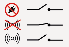
 |  | | | ||||
 |  |  |  | ||||
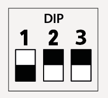 |  | 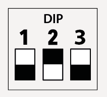 |  | ||||
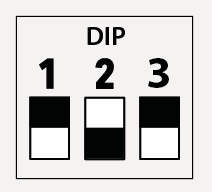 |  | 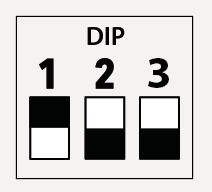 |  | ||||
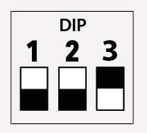 |  | 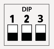 |  | ||||
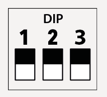
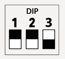
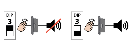
CONTROL INPUT | AUDIO ALERT | |||||
Connect the input to an external signal to lock the switch and make the LED red. | Detection activates an audio alert. | |||||
| ||||||
| ||||||
For restroom application, see application note for more details. | ||||||


Status | Explanation / Solution |
|---|---|
Door does not open even when moving the hand towards the sensor. | Bad or no power supply. Check power supply. If LED switches on or flashes, power connection is OK. |
Incorrect wiring / connection. Check wiring and relay connection. | |
Detection range is too short.
| |
Sensor stays in detection. | The environment influences the good functioning of the sensor. Remove any moving object around the sensor. |
Incorrect wiring / connection. Check wiring and relay connection. | |
Door remains open after detection/activation. | Wrong output mode. Switch the output mode to PULSE. |
Incorrect wiring / connection. Check wiring and relay connection. |
Technology | Microwave motion sensor |
Radiated frequency | 24.150 GHz |
Radiated power | < 20 dBm EIRP |
Radiated power density | < 5mW/cm2 |
Detection range (hand) | +/- 10 to 60 cm if movement towards sensor at 90° (adjustable)* |
Detection mode | Motion (bidirectional) |
Speed of target to create detection | Min. 5Hz or +/- 3cm/s, Max. 200Hz or +/- 1.2m/s |
Supply voltage** | 12 - 24V AC +/- 10% (50 - 60 Hz). 12 - 24V DC +30% / - 10% |
Power consumption | < 1.5 W |
Output** Max. voltage Max. current Max. switching power | Electronic relay (galvanic isolation - polarity free) 42V DC/30 VAC 100 mA 15 W |
Output hold time | 0.5s (in PULSE mode) |
Temperature range | -20°C to +55°C |
Degree of protection | IP65 with front face and gasket mounted on a smooth surface |
Material | PMMA / PC Front face is treated with biomaster silver biocide tested to ISO 22196:2011. Please use biocides responsibly. |
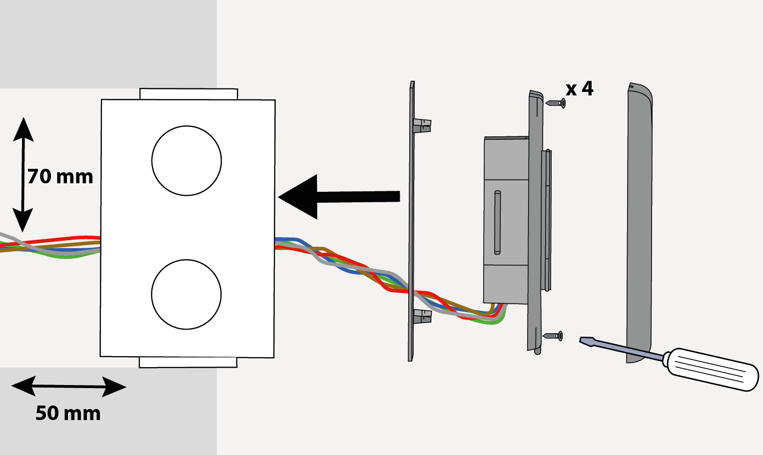
Dimensions | 80 x 80 x 21mm |
Wiring cable | Stranded cable up to 16 AWG - 1.5mm2 |
*An adjustement of the detection field below 10 cm is possible but the detection capability of the sensor can not be guaranteed. | |
![[Caution]](../css/image/caution.png) | Caution |
|---|---|
**External electrical sources must be within specified voltages, max 15W and ensure double insulation from primary voltages. |
BEA hereby declares that this product is in compliance with European directives 2014/53/EU (RED) and 2011/65/EU (RoHS). |  |
The complete declaration of conformity is available on our website. This product should be disposed of separately from unsorted municipal waste. |  |
| ||
WWW.BEASENSORS.COM BEA SA | LIEGE Science Park | ALLÉE DES NOISETIERS 5 - 4031 ANGLEUR [BELGIUM] | T +32 4 361 65 65 | F +32 4 361 28 58 | info-eu@beasensors.com| WWW.BEASENSORS.COM | ||

Manufactured by: BEA SA - LIEGE Science Park - Allée des Noisetiers 5 - 4031 Angleur - Belgium - T +32 4 3616565 - F +32 4 3612858 - info-eu@beasensors.com - www.beasensors.com | ||
PLEASE KEEP FOR FURTHER USE - DESIGNED FOR COLOUR PRINTING | ||

©BEA Sensors | Original Instructions |47.0997.01 - 07-25