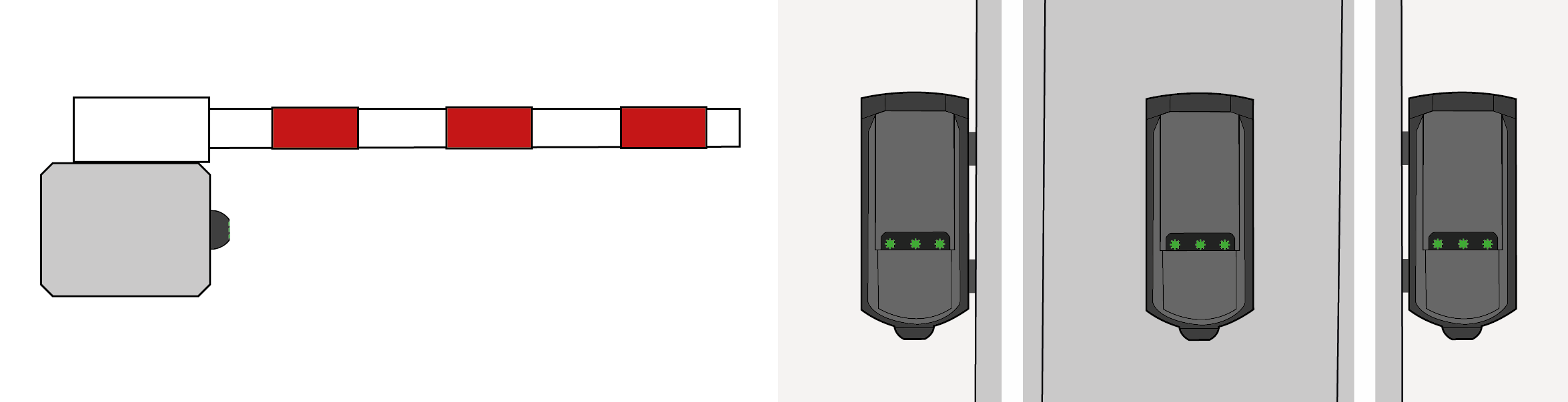
The EVOLOOP is an activation and presence sensor for automatic barriers with MoWa inside technology based on FMCW principles.

The EVOLOOP can be used as a safeguarding level D as described in EN 12453 (also called protection device). The use of a protectiondevice on its own cannot guarantee compliance with the requirements of EN 12453, it shall always be used in conjunction with a system to limit the forces of the barrier (safeguarding level C).
For protectioninstallation, make sure that the test input of the EVOLOOP is connected, and that it is tested before every movement of the barrier. If the test input is not used, the proper functioning of the EVOLOOP shall be checked at intervals not greater than 6 months.
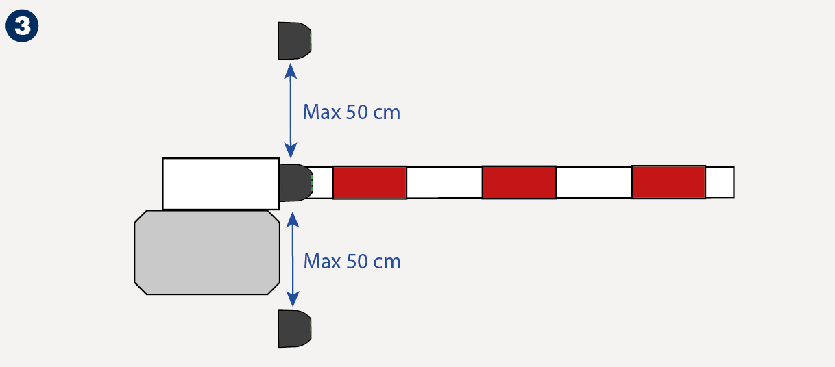
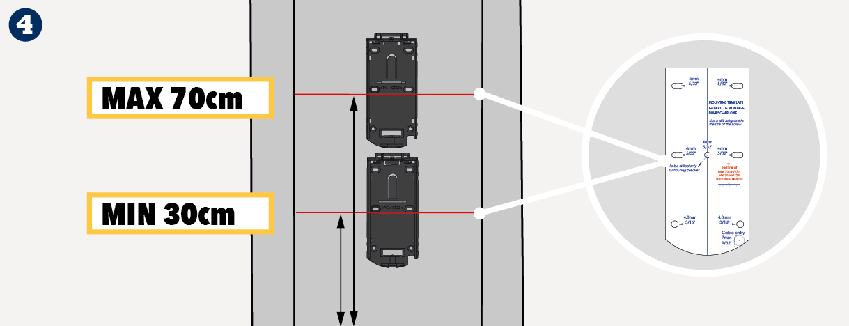
For protectioninstallation, make sure the EVOLOOP is positionned at maximum 50 cm from the boom (page 6 - point 3).
|
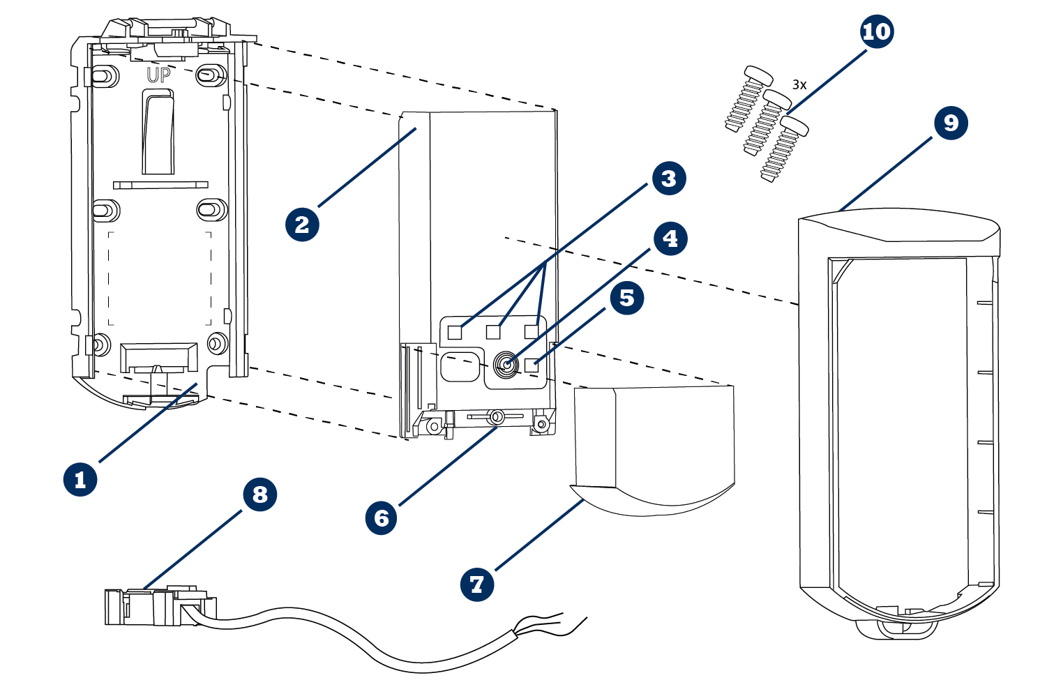
 | Mounting Support |  | Connector socket |
 | Sensor |  | Sliding Cover |
 | 3 virtual loop LEDS |  | Cable & Connector plug |
 | Push Button |  | Protective Cover (Plastic) |
 | Bluetooth® LED |  | 3 screws kit (M3 - Torx 10) |
Plastic version | Metallic version | ||
|---|---|---|---|
 |  |
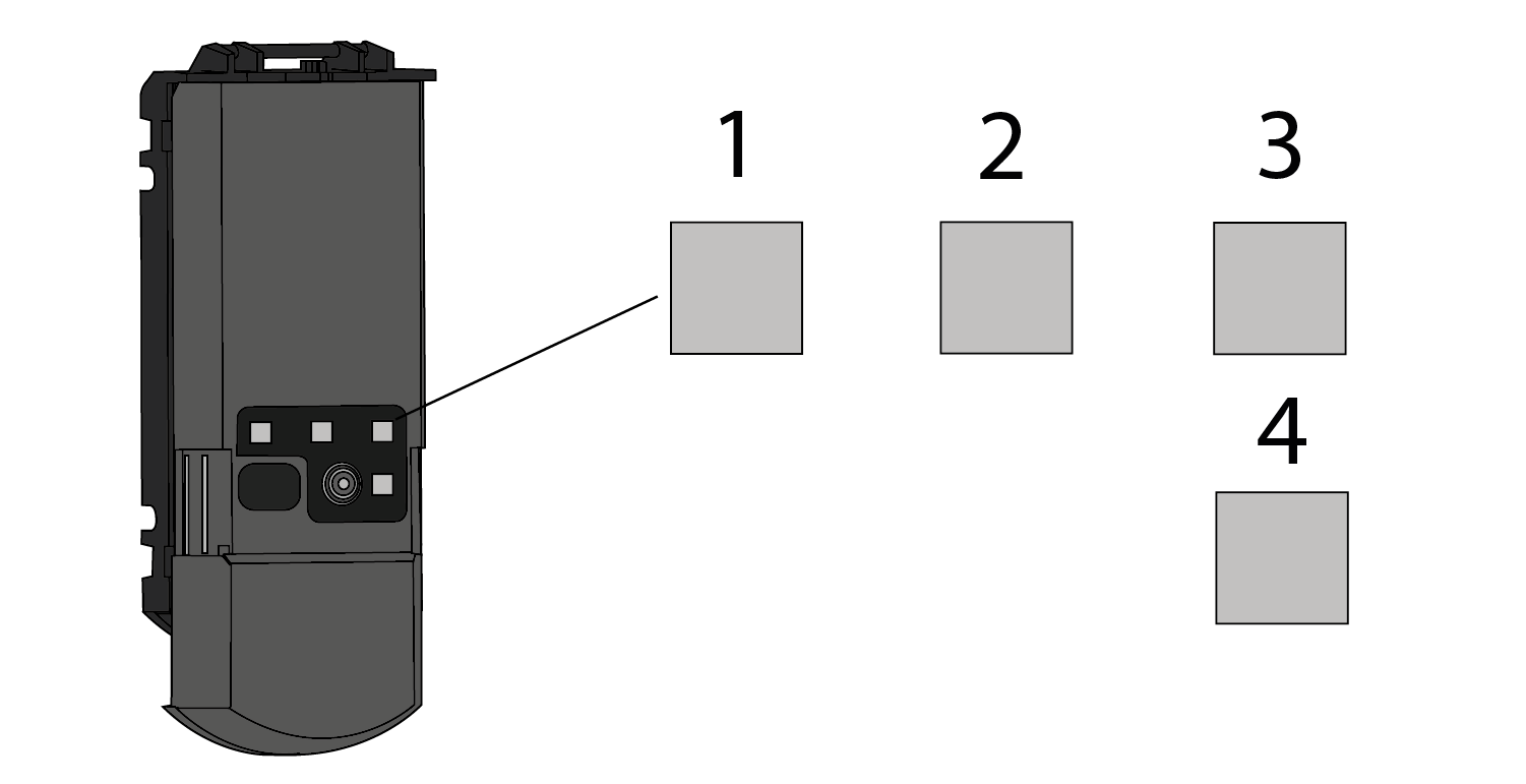 |  | LED indicating loop 1 status |
 | LED indicating loop 2 status | |
 | LED indicating loop 3 status or ERROR status | |
 | LED indicating Bluetooth® status |
LED - Working Principles
 | LED is OFF |  | Red LED blinks quickly |
 | Green LED is ON |  | Red LED and Green LED blinks |
 | Green LED blinks slowly |  | Orange LED blinks x times |
 | Green LED blinks |
LED – Loop Type
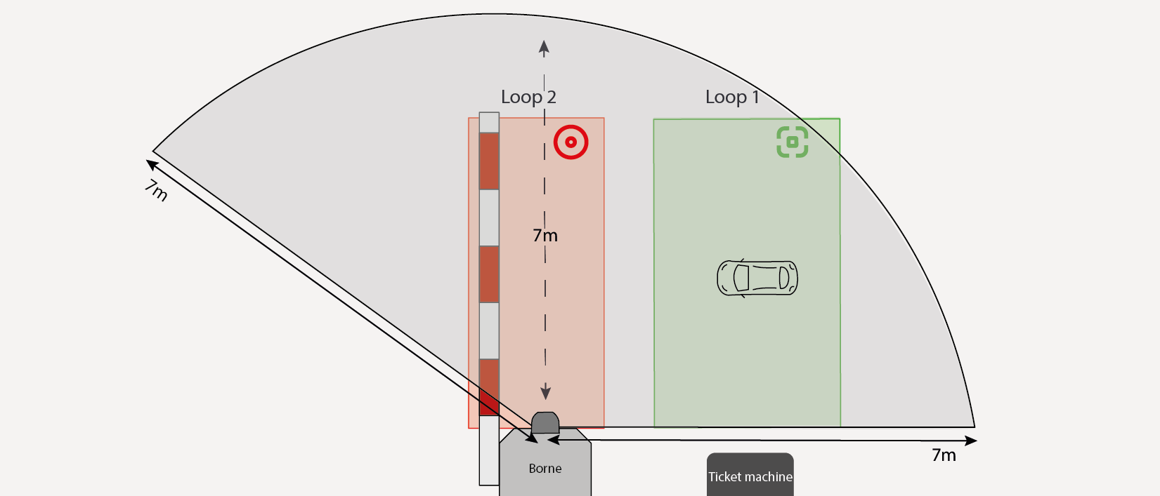
| Presence Loop: triggers output if a target is detected on the loop with selected type and direction. |
 | Protection |
 | Bluetooth® (only on LED 4) |
 | | | |
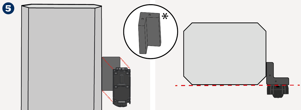
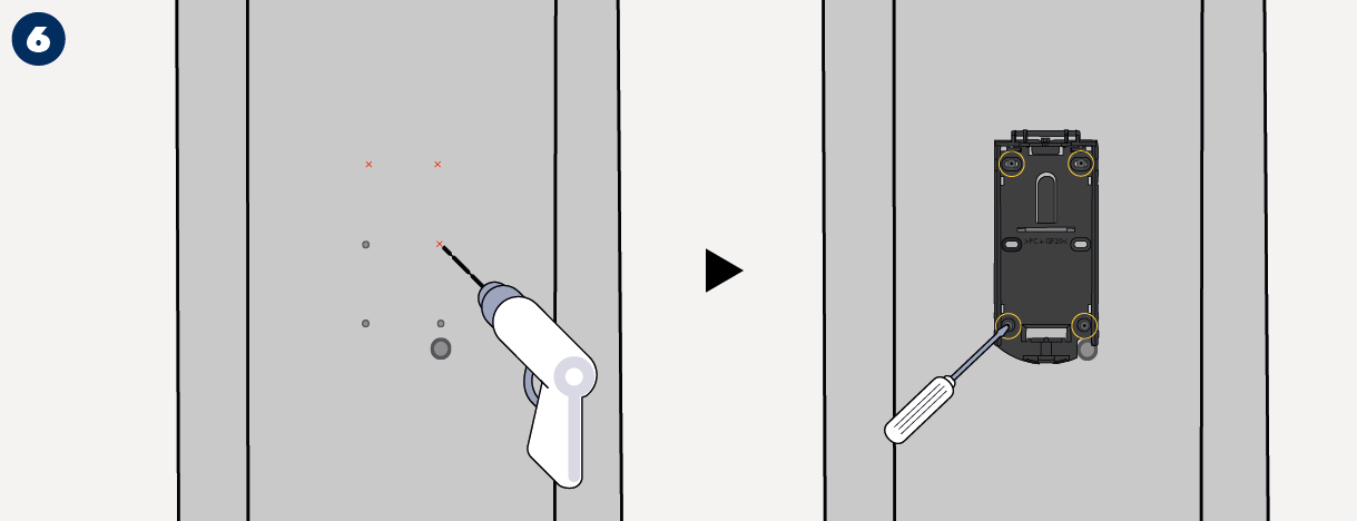
Always test the good functioning of the installation before leaving the premises. | Only trained and qualified personnel may install and setup the sensor. | Always mount the mounting support perpendicular to the barrier arm or boom. | Use stainless screws (M4) to fit the mounting support. Secure the mounting support on its support with at least 4 srews. |
 | | | |
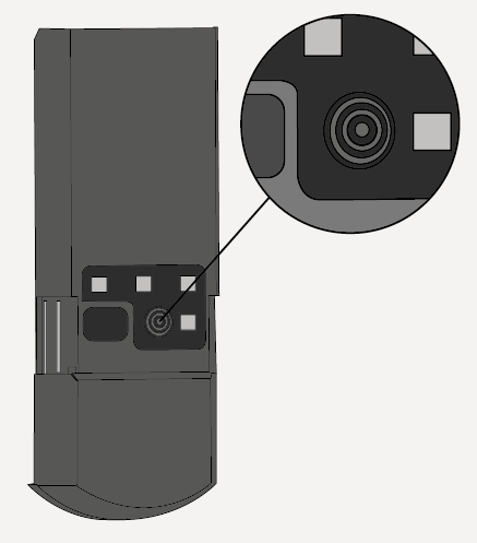
Avoid vibration, condensation, sudden and extreme temperature changes | Do not cover the product front face | Avoid presence of metalic parts in the sensor's close environment that may obstruct the detection field. |
| | |
Make sure the front face is clean | ||
| | |
Avoid direct exposure to high pressure cleaning | The warranty is invalid if unauthorized repairs are made or attempted by unauthorized personnel. | Do not apply solvent-base or oily product on the sensor. |


| |
| |
 |
|
 |
|
 |
|
 |
|
 |
|
| |
| |
| |
|
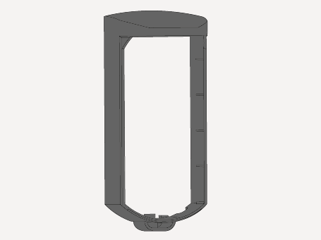 | 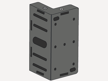 | 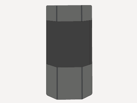 | 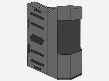 |
PROTECTIVE COVER | BRACKET | HOUSING | BRACKET & HOUSING |
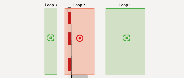 | ||
Detection on loop 3 triggers OUT 3 | Detection on loop 2 triggers OUT 2 | Detection on loop 1 triggers OUT 1 |
Presence for acknowledgment | Protection | Presence for activation |
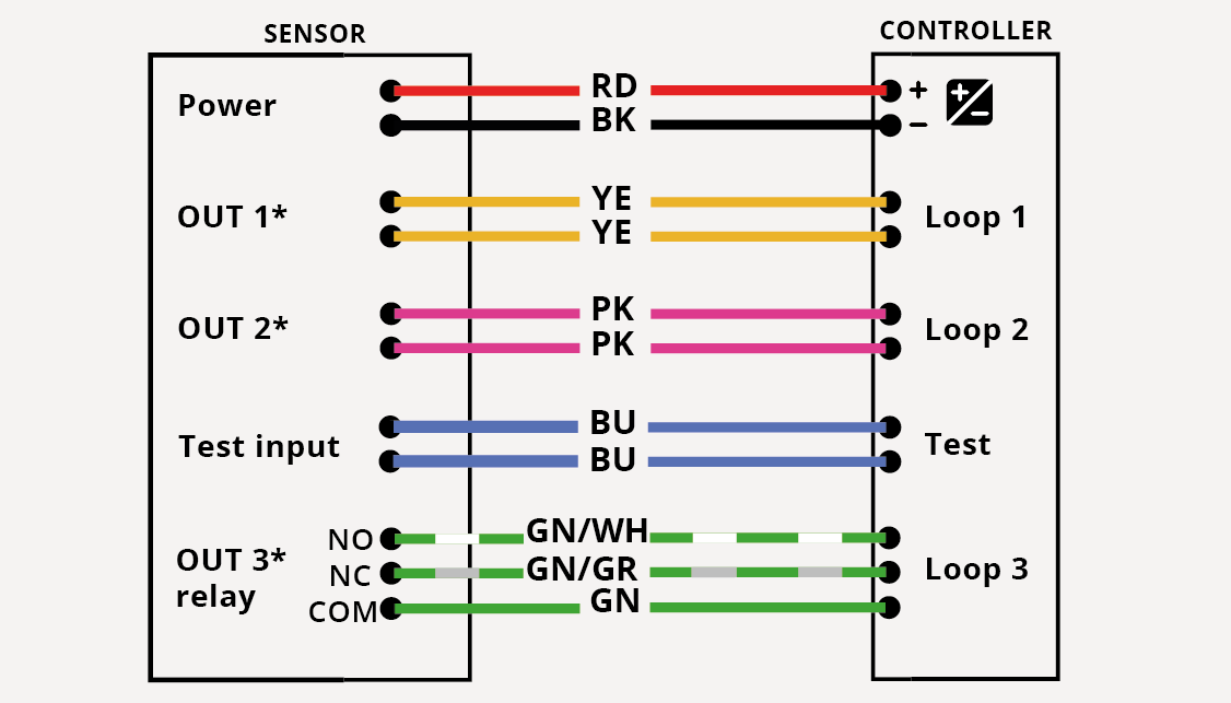 | ||
*Always check output logic factory values. | ||
Scan the QR code or open the following link to download the mobile application and install it. https://play.google.com/store/apps/details?id=com.beasensors.evoloop https://apps.apple.com/us/app/evoloop/id6474297732 |  |  |
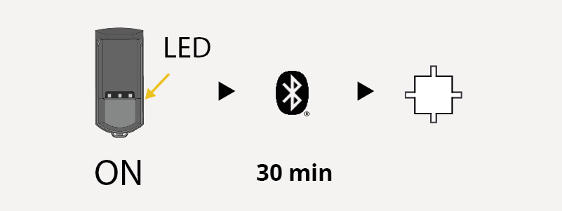 | At power ON or after a power cycle,the Bluetooth® keeps activated 30 minutes after last use and then turns off automatically. The white Bluetooth® LED blinks (1Hz). |
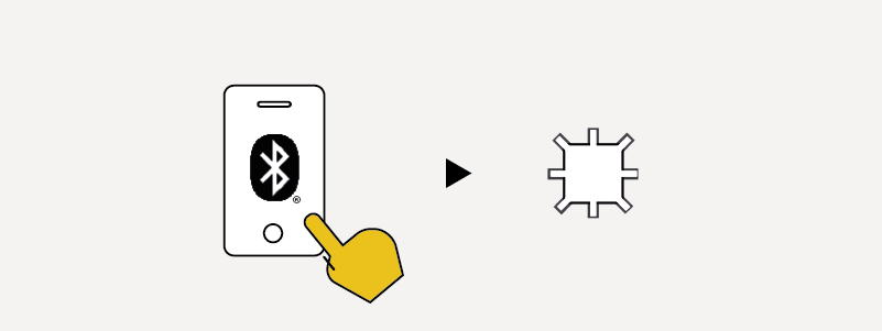 | Open the Evoloop mobile app and connect it to the sensor. During pairing, the Bluetooth® LED blinks quickly. |
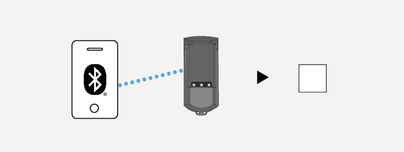 | Once paired, the white Bluetooth® LED is on. |
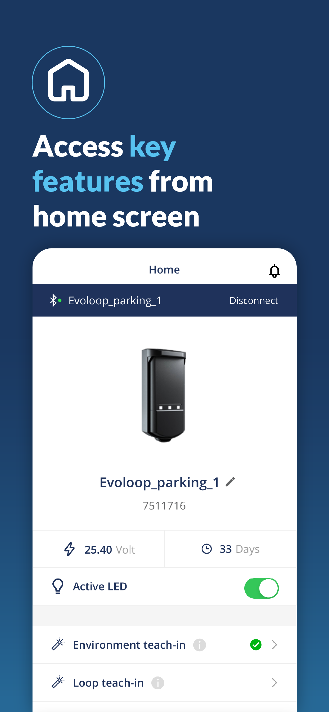
Home | Teach-in | Setting | Viewer | Diagnostic |
 |  |  | 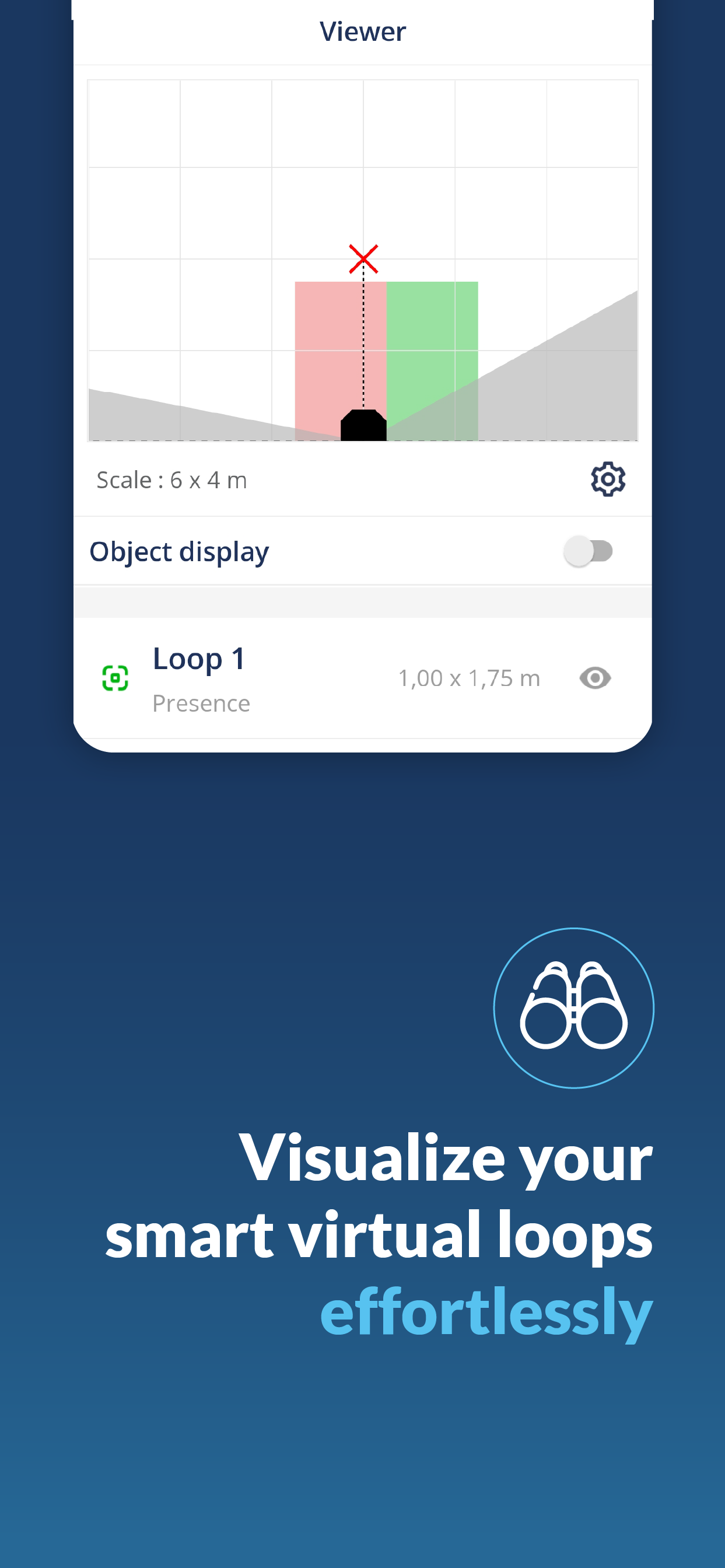 |  |
The Bluetooth® word mark and logos are registered trademarks owned by Bluetooth SIG, Inc. and any use of such marks by BEA sa is under license. Other trademarks and trade names are those of their respective owners |
 | Push 1x | Wake Up from idle mode - Bluetooth® is activated. (White blinking) |
Push 1x | Launch full teach-in, when sensor is awake. (Red/Green blinking) | |
Push 2x | Launch loop teach-in, when sensor is awake. (Alternative green blinks) | |
Push > 3s | Service mode activation/deactivation |
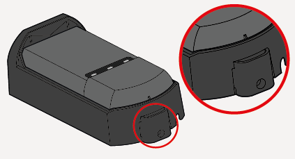
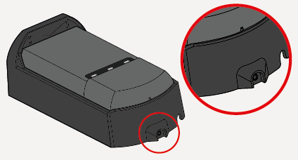
Put the sliding cover back in place. | |
Put the protective cover back in place. If needed use the screw to firmly fix the cover. | |
With both the plastic and metallic versions you can use screws (TORX 10). |
![[Note]](../css/image/note.png) | Note |
|---|---|
Make the teach in with mobile app or using button. |
![[Caution]](../css/image/caution.png) | Caution |
|---|---|
It’s mandatory to follow the installation steps in order to correctly commission the sensor and ensure the good functioning of the barrier. 1. Sensor is mounted. 2. Sensor must be correctly wired. 3. Barrier must be opened |
Initial State When the sensor is out of the box or if it has been reset to factory values, the orange LEDs blink and outputs activated. Before launching the teach-in, make sure the environment is clear of any objects and that you’re standing outside of the field. | 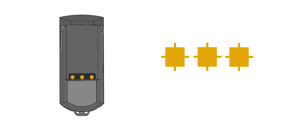 |
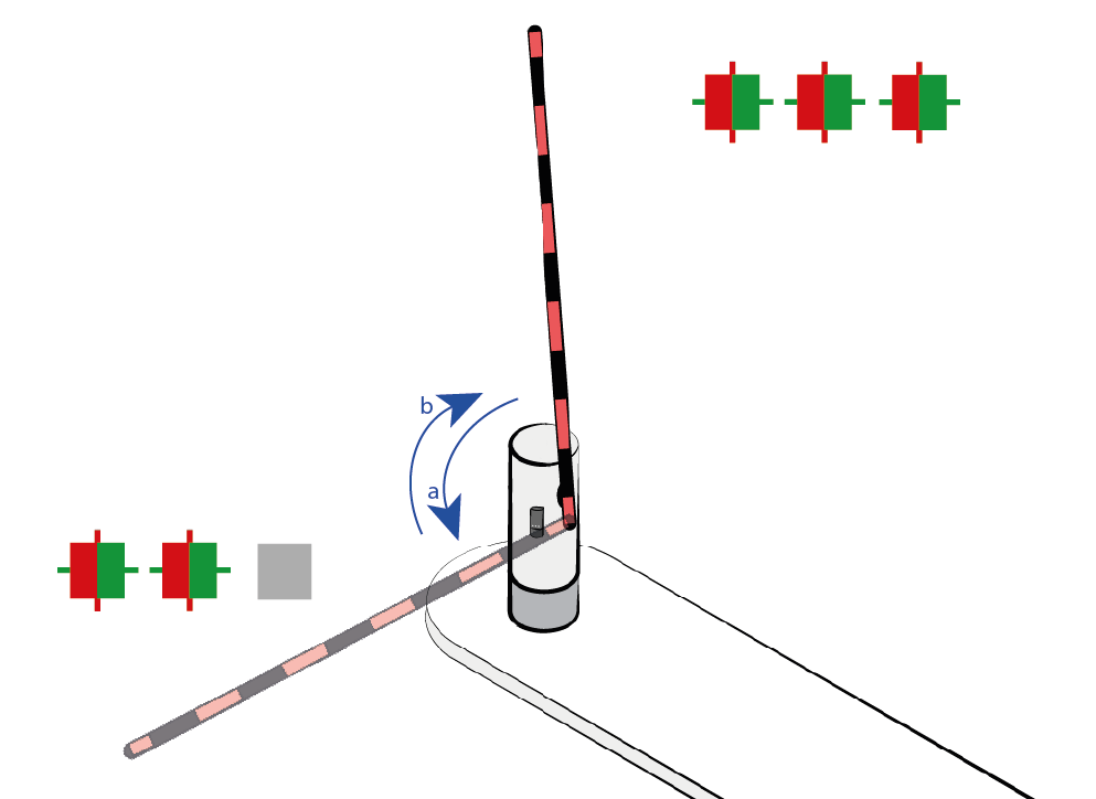
| ||||||||||||||||
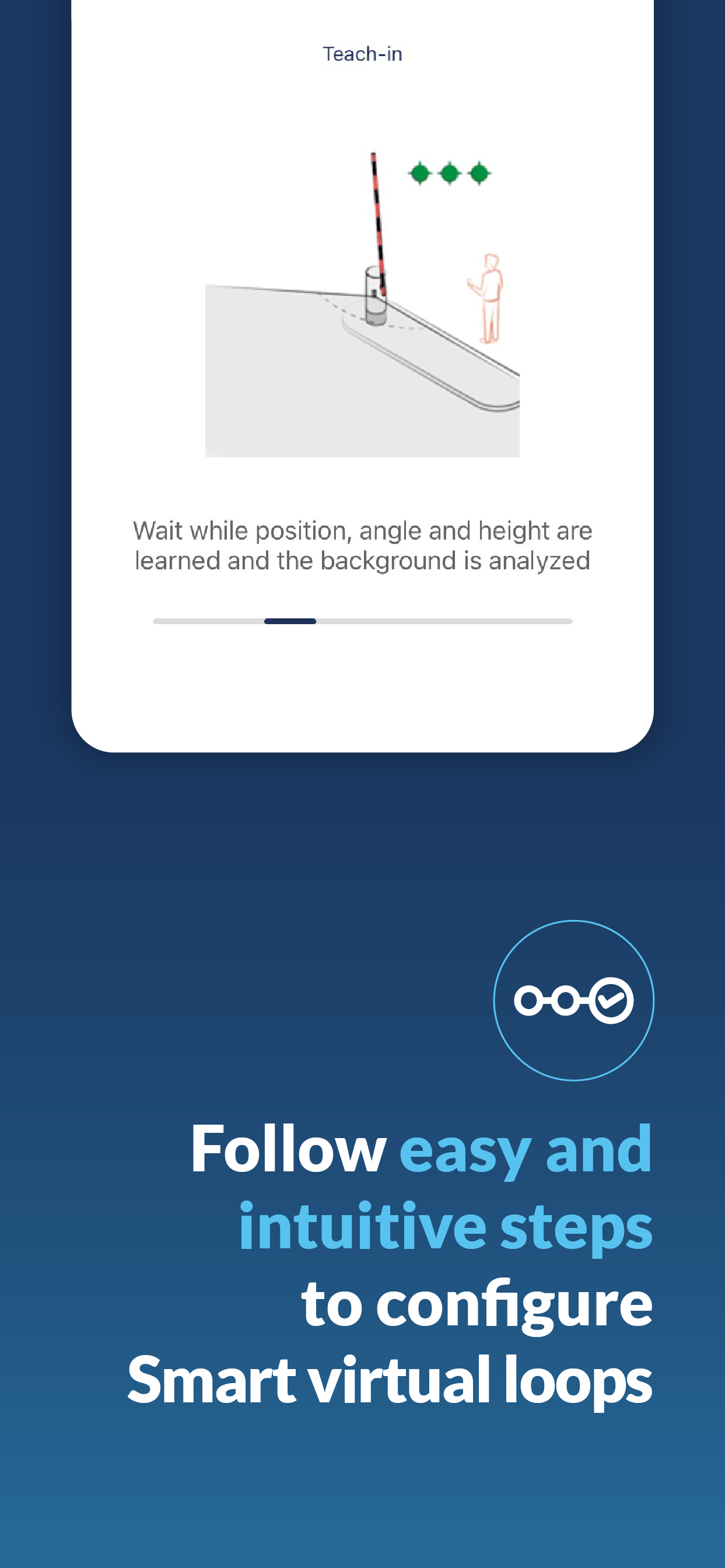
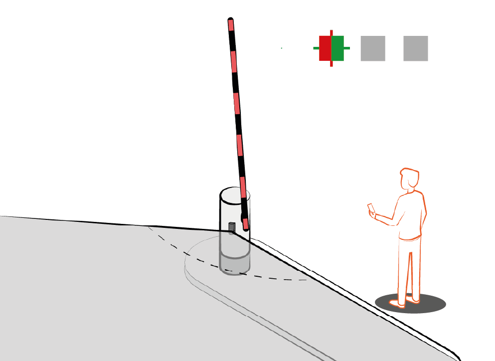
Once the boom teach-in is completed successfully, the product waits for you to indicate the length of the boom. Stand in front of the sensor at a distance equal to the boom length or the road width. During the waiting period, the green LEDs blink. | 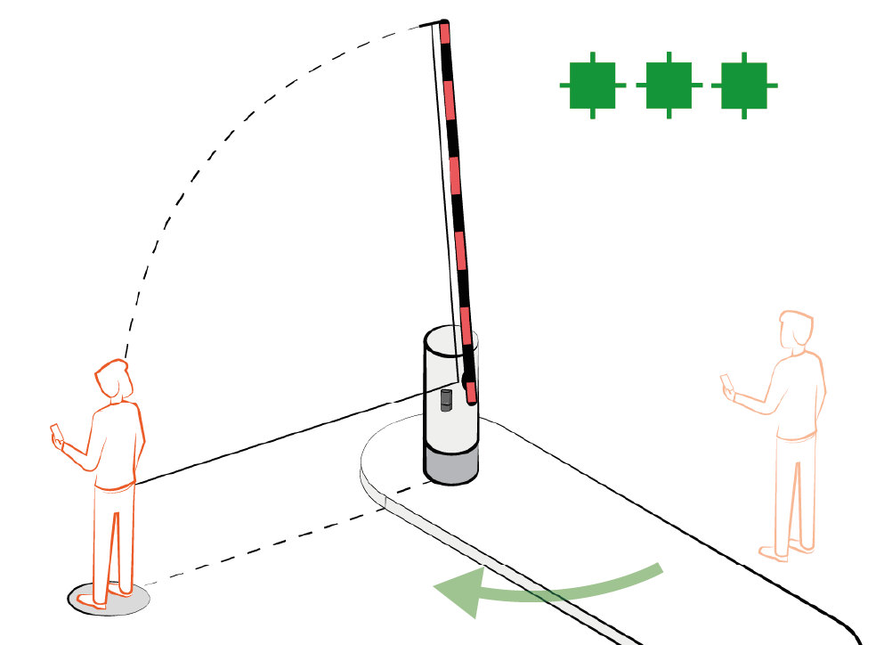 | |||||||||||||||
Stand still the LEDs blink red to indicate the sensor has locked your position and the process is completed successfully. | 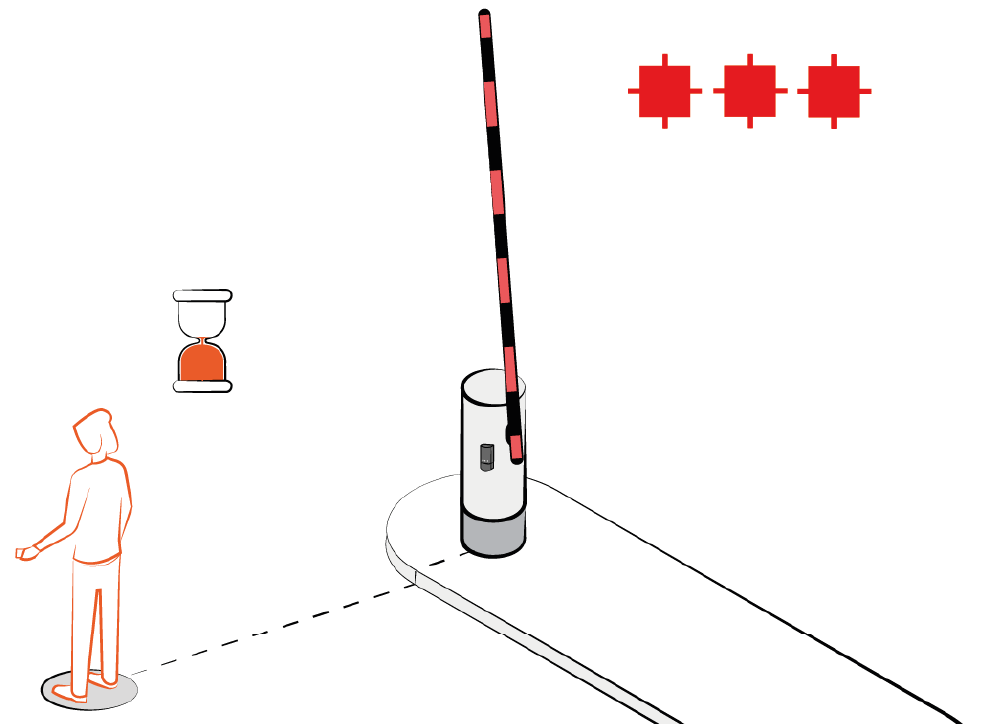 | |||||||||||||||
| Caution |
|---|---|
It’s mandatory to follow the installation steps in order to correctly commission the sensor and ensure the good functioning of the barrier. |
| Note |
|---|---|
Mobile App Loop configuration is possible by using the app. |
Select the loop you want to configure by static Teach-In Loop 1, push when LED 1 is ON, Loop 2, push when LED 2 is ON Loop 3, push when LED 3 is ON | 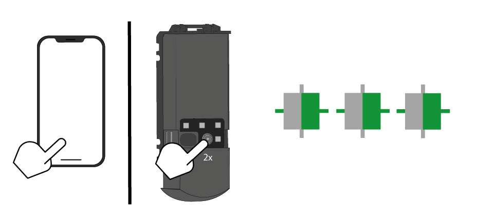 |
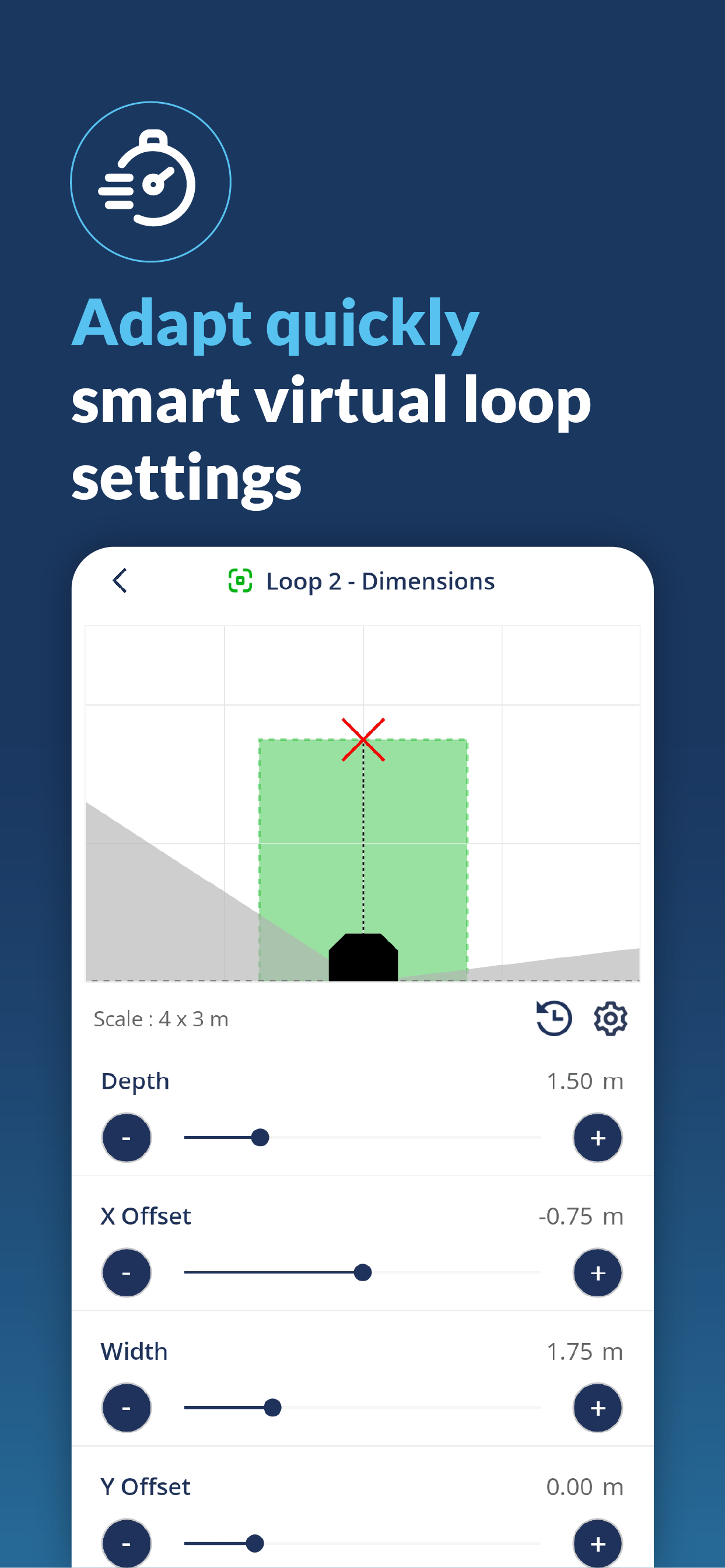
When the green LEDs start blinking slowly, go to the centre of the loop and stand still. Once the red LEDs are blinking, the teach-in of the loop is completed successfully. By default loop's depth is set to 1.5m and width to distance learned during edge teach-in | 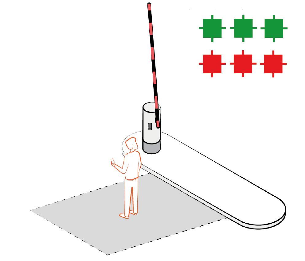 |
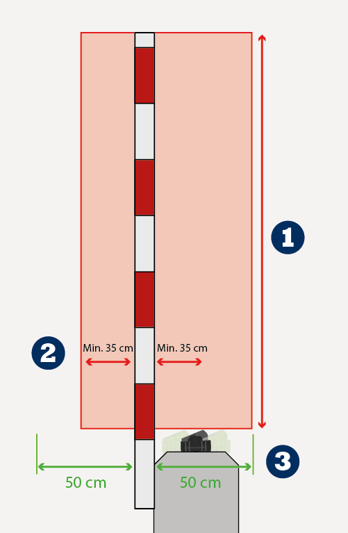 | 1) Set the protection |
2) Set the protection | |
3) Always rotate the sensor so that the Evoloop is pointing towards the protection |
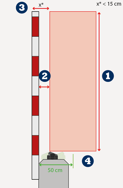 | 1) Set the protection |
2) Set the protection | |
3) This type of installation can only be used if the distance between the protection | |
4) Always rotate the sensor so that the Evoloop is pointing towards the protection |
LED | Status | Explanation/Solution |
|---|---|---|
 | The error LED (3) is on permanentely | The sensor encounters a memory problem. Replace sensor. |
 | LED 1 - 2 - 3 are blinking orange | The product is in initial state Initiate a teach-in to commission the sensor use the mobile app or the button |
 | The error LED (3) blinks 1x | The sensor signals an internal fault Cut and restore power supply. LED blinks again, replace sensor |
 | The error LED (3) blinks 2x | Power supply is out of limit.
Internal temperature is too high. Protect the sensor from any heat source (sun, hot, air...) |
 | The error LED (3) blinks 3x | Internal communication error. Cut and restore power supply. LED blinks again, replace sensor. |
 | The error LED (3) blinks 4x | Masking Error Something close to the sensor is masking part of the detection field.
|
Technology | FMCW, Mowa inside (microwave) |
Radiated frequency | 60 GHz |
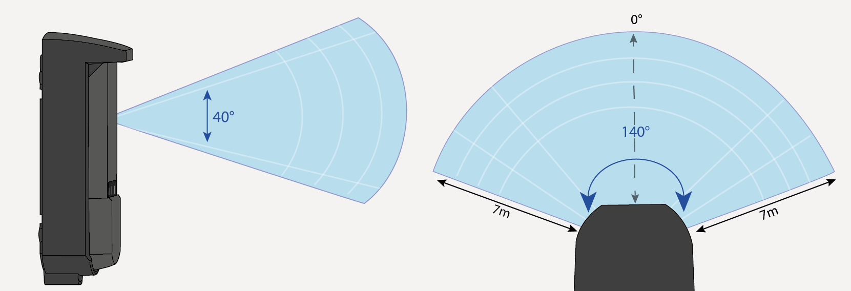
Max Detection Field | Up to 7m |
Radiated power | < 20 dBm EIRP |
Radar Field of view | 140° opening field and 40° in elevation |
Reference body for Safeguarding Level D | Corner reflector with RCS = 0.17m² |
Antenna angle adjustment | -20° to +20 ° |
Supply voltage* | 12 – 30V DC +/-10% - 12-24V AC +/-10% |
Max Power consumption | <3W |
Peak Current at power-on | 1.3A |
Cable Length | 3m (standard) |
Response Time | Typical 100ms (max 250ms) |
Test input Max. contact voltage Voltage Threshold | 1 optocoupler (galvanic isolated – polarity free) 30 V DC (over voltage protected) Log. H: >8 V DC; Log. L: < 3 V DC |
LED | 3 RGB LED and 1 white LED for Bluetooth® |
Dimensions | 50 mm x 150 mm x 68mm (form factor) |
Temperature range | -25°C to +55°C **; 0-95% relative humidity, non condensing |
Degree of protection | IP65 (IEC/EN 60529) |
Material | PC / ASA / Aluminium ADC12 – black color |
Bluetooth® | Operating bandwidth: 2402 MHz – 2480 MHz Maximum transmitted power: 12 dBm |
Outputs* | |
Electronic relays (galvanic isolated – polarity free) | 2 |
Max. switching voltage | 35 V DC / 24 V AC |
Max. switching current | 80 mA (resistive) |
Switching Time | tON= 5ms; tOFF = 5ms |
Output Resistance | Typ 30 ohms |
Voltage drop on output | < 0,7V @ 20mA |
Leakage current | <10µA |
Relay | 1 |
Max. switching voltage | 30VAC / 42V DC |
Max. switching current | 1A |
Max. switching Power | 30W |
| Caution |
|---|---|
* External electrical sources must ensure double insulation from primary voltages. ** When using AC supply, the maximum temperature is limited to 50°C. |
Specifications are subject to change without prior notice. All values measured in conditions and with a temperature of 25°C |
BEA hereby declares that this product is in compliance with European legislation 2014/53/EU (RED) and 2011/65/EU (RoHS). The complete declaration of conformity is available on our website. |  |
This product should be disposed of separately from unsorted municipal waste. |  |
| ||
WWW.BEASENSORS.COM BEA SA | LIEGE Science Park | ALLÉE DES NOISETIERS 5 - 4031 ANGLEUR [BELGIUM] | T +32 4 361 65 65 | F +32 4 361 28 58 | info-eu@beasensors.com| WWW.BEASENSORS.COM | ||

 |
Manufactured by: BEA SA - LIEGE Science Park - Allée des Noisetiers 5 - 4031 Angleur - Belgium - T +32 4 3616565 - F +32 4 3612858 - info-eu@beasensors.com - www.beasensors.com | ||
PLEASE KEEP FOR FURTHER USE - DESIGNED FOR COLOUR PRINTING | ||

©BEA Sensors | Original Instructions | 47.0859.02 | 05.25